


Name and draw five appliances in your home that need electricity to work.
Electric circuits
- What is electricity?
- How do we construct a simple electric circuit?
- What are electric circuit components?
- What is the function of each circuit component?
- What is the difference between a closed and open electric circuit?
Use a Learning Cycle approach to teach Electric Circuits:
- Engage: Assess the learners' prior knowledge by engaging them with either questions or a task related to the new concept to be learnt. The activities should provide an opportunity for learners to talk about their prior experiences with the concept.
- Explore: The teacher provides a common activity, task or series of activities in which learners engage. Part of the exploration phase could be for learners to predict what they think would happen during an activity. The activities should provide learners the opportunity to collect and organise data that will allow them to generate explanations for the phenomenon under investigation.
- Explain and reflect: The teacher leads a discussion around the learners' data. The teacher introduces vocabulary, ideas, concepts, etc. as necessary. The teachers and learners may co-construct an explanation for the phenomenon under investigation.
- Elaborate or apply: The teacher provides opportunities for learners to extend their understanding by providing new and/or related experiences for them to apply what they have learnt.
- Evaluate: Assess the learners' understanding of the concept/phenomenon through any appropriate manner.
Asimple circuit
Many misconceptions develop in learners' minds about electricity and electrical phenomena if teachers are not careful about the correct use of scientific language and appropriate conceptual development of these ideas. Teachers speak, for example, too loosely about concepts like electricity, electric current and charge as if these concepts are the same thing. Learners were first introduced to electricity in Gr. 5 and this year the concept will be built upon much further.
If we think of the world that we are currently living in, one of the things that we encounter every day and almost everywhere is electricity.
What do you know about electricity?
In step 1 of the Learning Cycle, learners must brainstorm what they know about electricity.
Think about electricity and write your answers or responses in the spaces provided below.
QUESTIONS:
Name five applications (uses) of electricity in your neighbourhood.
Name five applications of electricity in your school.
Why is electricity important to you?
Why is electricity important for your city or town?
Why is electricity important for your country?
You are building a brand new house. You want an electric stove in your kitchen. Name all the things that must be done for your stove to work.
Electric stove is connected to the electrical supply from a supplier like ESKOM, also called the mains supply. An electrician must install the connecting wires in the house.
Cellphones work with electricity. How does your cellphone make use of electricity?
Cellphone has a battery.
What is the difference between the way we can get an electric stove and a cellphone to work?
A cellphone works from a rechargeable battery. The stove is connected to the mains supply. The cellphone battery is recharged from the same electrical supply as for the stove.
-
What would you say electricity is?
Electricity is the name given to a wide range of electrical phenomena. It underlies in one form or another almost everything around us. It has applications in science, engineering and technology. It has to do with the physical phenomena associated with the presence and movement of electrically charged objects. Electricity includes a wide variety of well-known electrical effects, such as lightning, static electricity, electromagnetic induction and an electric current in an electric wire.
We are using electricity all the time. We need to understand what it is about and how to use it safely and correctly.
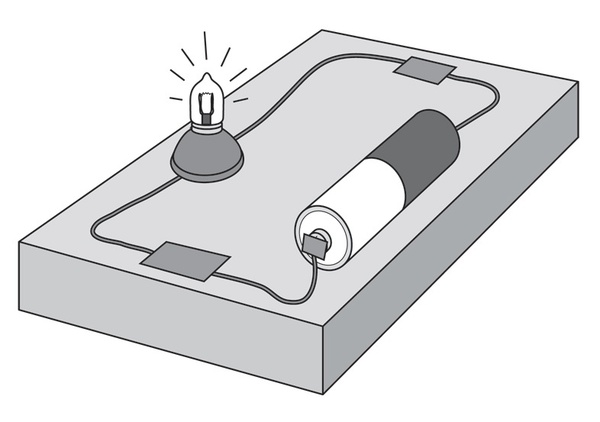
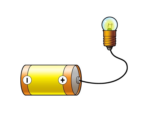
Have you ever used a flash light (torch)? What is it used for? How do you get the flash light to work? Let us try to get the bulb of a torch to work. We want to do this without using the torch itself.
How to get a light bulb to work
In step 2 of the Learning Cycle, learners explore how to construct a simple electric circuit by getting a light bulb to work.
Before getting the learners to do the activity, do it yourself and ensure that it works with the batteries and bulbs available. Some bulbs might need a battery of more than 1.5 V. The best would be to find bulbs that would work from 1.5 V. The wires could be obtained from any electrical appliance not used anymore. If you cannot find a bulb that would work from 1.5 V, then try a 9 V battery.
There is a YouTube video (8-9 minutes) that might be helpful to teach this unit.
MATERIALS:
- D-size battery (1.5 V)
- torch light bulb
- three pieces of electric wire 15-20 cm long with the ends about 1 cm stripped of the plastic insulating material
- adhesive tape or Prestik
- piece of cardboard
- two thumbnails with metal (brass) tops (remove plastic if tops are covered)
- a metal paper clip (remove the plastic if covered)
INSTRUCTIONS:
Electrical contact is important in all the activities that follow. If the connections or switches do not work later on, ensure that there is electrical contact (metal on metal) at each contact point in the circuit. Take care to indicate this to the learners as well.
- Work in pairs.
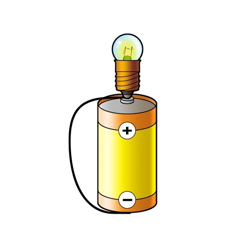
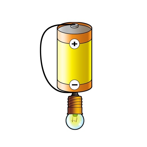
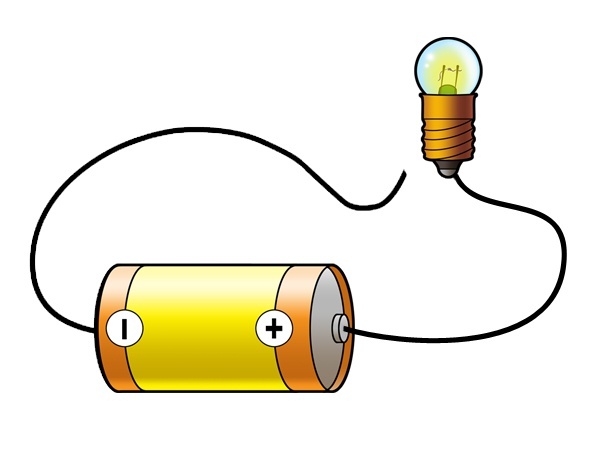
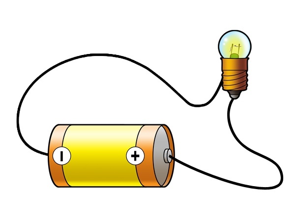
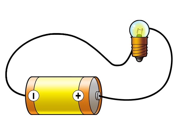
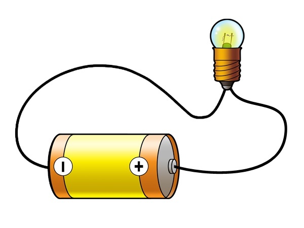
- The pictures below show four ways of connecting the battery and the bulb using only ONE wire.
- First predict if the bulb will light.
- Then do the connection and test if your prediction was correct.
|
Circuit |
Prediction - Will the bulb light up? (Yes or no) |
Experiment - Did the bulb light up? (Yes or no) |
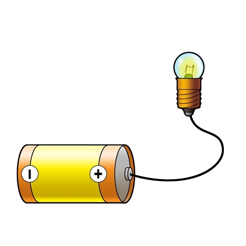 |
No |
|
 |
No |
|
 |
Yes |
|
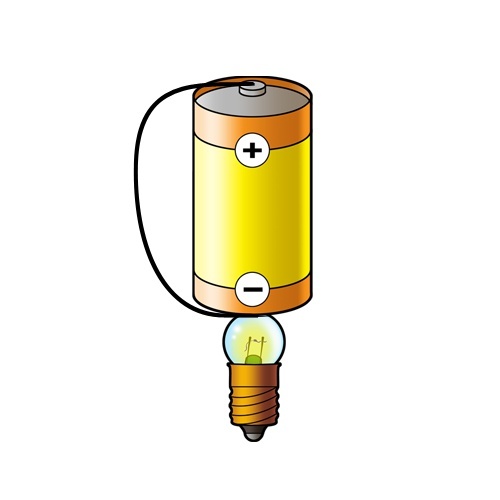 |
No |
It is NOT important for learners to get the predictions correct! This is part of a learning process that works towards conceptual understanding and coherence. However, predictions are based on some reasoning, and so it IS very important that they are allowed to reflect on why their predictions were incorrect. Many learners leave the school system believing that predicting is guessing with no follow-up.
- How many other ways can you light the bulb? Try different connections. Draw those that work and those that do not work in the table below.
Learners might come up with more connections that do not work rather than connections that would work. The bulb could be put on the negative side of the battery as well to get a connection that can work.
|
Connections that work |
Connections that do not work |
-
Describe in words what you did to get the bulb to light.
Teacher note: The core objective here is to form a complete path for electricity that connects one terminal of the battery to one terminal of the light bulb and the other to the other.
- You have just constructed a simple electric circuit! Let us now see if you can also find a way to light the bulb using two wires.
- The next pictures show four ways of connecting the battery and the bulb with TWO wires.
- Use adhesive tape or Prestik to keep the wires attached to the battery. Do the same as before:
- First predict if the bulb will light.
- Then do the connections and test if your prediction was correct.
|
Circuit |
Prediction - Will the bulb light up? (Yes or no) |
Experiment - Did the bulb light up? (Yes or no) |
 |
No |
|
 |
Yes |
|
 |
No |
|
 |
No |
- Try some more ways to connect the battery and the bulb with two wires. Draw one example of a setup that worked and one that did not work.
|
Set up that works |
Set up that does NOT work |
- You have constructed another example of an electric circuit!
-
Describe in words what you have done to get the bulb to light in the case of using two wires.
In step 3 of the Learning Cycle, a discussion should follow. Introduce some of the vocabulary, ideas and concepts. Together with your learners you must co-construct an explanation for the phenomenon under investigation (why the electric circuit works or does not work).
Now that we have investigated different ways of making a simple circuit, let's define it in more detail.
Electric circuits have different components. What does 'component' mean? Look up the definition for component in your dictionary and write it below.
A part or element of a larger whole, especially a part of a machine or vehicle.
A simple electric circuit has at least three components:
- Asource of energy, such as a battery.
- Conducting material, such as the electric wires.
- A device that transfers the energy for a useful purpose, such as the bulb that provides light.
Note that the diagram has an additional component: a bulb holder. Be aware that this obscures the actual connections to the bulb.
Do you think there is something flowing through the bulb when it lights up? When we connect the bulb so that it lights up there is something flowing through the whole circuit. When it does not light up, we have not made a proper or complete pathway for electricity. This flowing `thing' is called electric current. If the bulb lights up, we say there is an electric current in the circuit. The electric circuit is a system for transferring energy. Think again about the circuits that you have constructed so far.
What are the conditions for the bulb to light up?
The circuit should have at least all three components as mentioned above. The circuit should be closed. The connections should provide electrical contact (metal on metal).
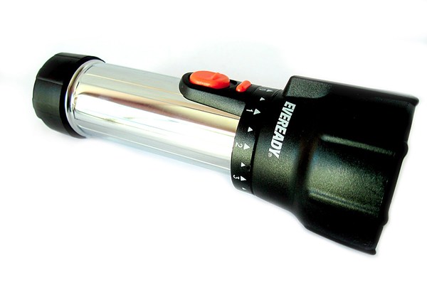
Let us look at the torch once more:
- Is the bulb providing light all the time?
- When does it provide light and when not?
- What do we call the component of the flashlight that allows us to turn the light on and off?
A switch is used to put an electrical device on or off. But how does it work?
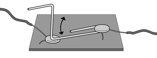
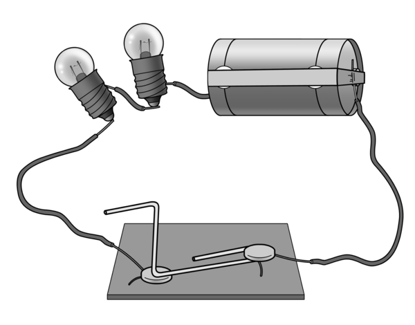
Investigating how a switch works
MATERIALS:
- apaperclip
- two thumbnails (drawing pins)
- a piece of cardboard
- a torch bulb
- 3 pieces of wire
- batteries
INSTRUCTIONS:
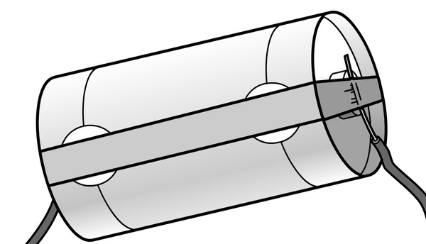
- To make the switch, bend the paper clip as shown in the diagram.
- Pin the ends of the two wires down on the cardboard with the thumbnails. One of the thumbnails should also pin down the paper clip.
- The other end of the paper clip can be moved to make contact with the second thumbnail or not.
- Move the paper clip away so that it does not make contact with this thumbnail.
- We now want to use the switch. Use the same setup for a simple electric circuit with a bulb, battery and 2 wires as you did in the last activity.
- Connect the paperclip switch to the battery by using a third electric wire. Remember to keep the wire ends in position with cellotape or Prestik.
QUESTIONS:
Move the paper clip onto the second thumbnail. What happens?
The bulb lights up.
Move the paper clip away from the second thumbnail? What happens now?
The bulb goes out.
Explain why you think the paper clip and cardboard device can be called a switch.
We already said that a switch is used to turn an electrical device on or off. We can also say that a switch is used to close or open an electrical circuit. When the switch is on, the circuit is closed. An electric current then exists in the circuit. We could also say there is an unbroken electric pathway in the circuit.
When the switch is off the circuit is open. In this case there is no electric current in the circuit. The electric pathway is now broken.
Name four other electrical appliances in your home that has a switch.
Circuit components
We need to have a closer look at the components in the electric circuit. This will help us to understand how a circuit works.
For the following activities, it is best if learners can see the actual components mentioned (different batteries, light bulbs, etc), but if that is not possible, then make reference to the photos included to complete the questions. This will help learners to realise that the circuits they are building in class represent bigger circuits that are all around them in their daily lives, whether it is the circuit in a car or a circuit in a house or the classroom when you turn on the light.
Batteries come in all shapes and sizes
MATERIALS :
-
aselection of different batteries, such as:
- atorch battery
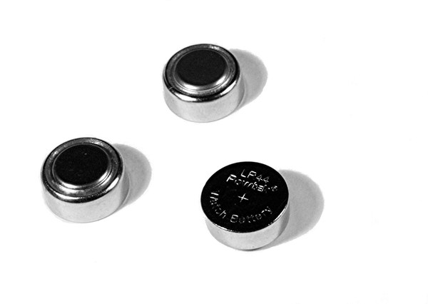
- a watch battery
- a cellphone battery
- a hearing aid battery
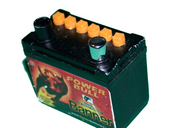
- a car battery (or photo)
INSTRUCTIONS:
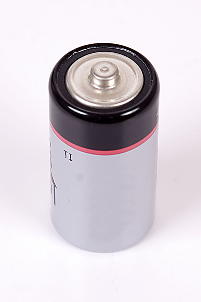
- Look at a typical torch battery.
-
Describe in words what the battery looks like. Refer specifically to the ends of the battery.
The battery is shaped like a cylinder. One end is flat, and the other end has a knob. The battery is covered in a metallic material.
-
Look carefully to see if you can identify a positive (+) and a negative (-) sign on the battery. Which side of the battery is marked with a positive sign and which side with a negative sign?
The side with the knob is the positive end, and the flat side is the negative end.
- Below is an image of a typical torch battery. Indicate on the image which is the positive and which the negative pole of the battery. Use a (+) and (-) sign as you have seen it on the battery.
- Batteries come in all shapes and sizes. Look at the pictures below of different batteries.
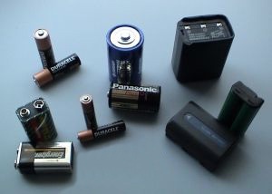
- You may be lucky enough to have different types of batteries in your class, such as from a watch, a cellphone or a car. If not, ask an adult in your family to show you a car battery, a cellphone battery and a battery used in a watch after school.
- Draw sketches of such batteries below. Indicate on each sketch the positive and the negative pole of each kind of battery. Below are some photos to help you if you cannot find these batteries.
|
Car battery |
Cellphone battery |
Watch battery |
For some appliances it is very important that the batteries are put correctly into a specific position. Why do you think this is the case? This is because the battery is used to get an electric current in the appliance and in some appliances the electric current can only go in a specific direction through the appliance. To prevent the appliance from being damaged, the battery must be inserted in the correct direction.
Investigating bulbs
MATERIALS:
- atorch bulb used in the simple circuit activity
- a light bulb for a house fitting
INSTRUCTIONS:
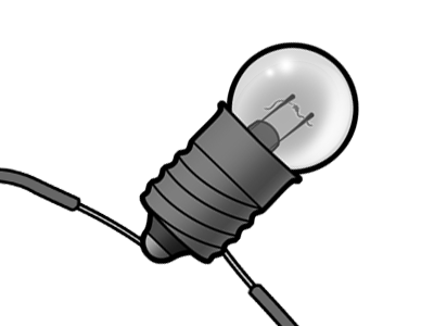
- Compare the bulb that you used for the circuits with a light bulb that is used in a light fitting in a house or in your classroom. Below is a close up of a light bulb used in a house fitting if you do not have an actual one.
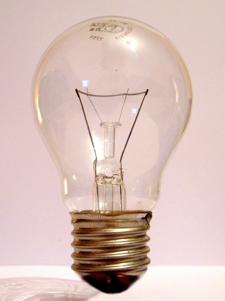
- Try to identify the following six parts of the bulb: glass cover, bottom metal casing, two metal pins, very thin wire between the metal pins, glass piece that keeps the metal pins in position and a metal contact point at the bottom. Label all parts of the bulb on the sketch below.
- Assume the bulb is connected to a battery. Use a bright colour pencil or pen (red if possible) to draw the path of the electric current through the bulb.
The path should start at the metal casing, then up one of the metal pins, then through the thin wire, then down the other pin to the connection point at the bottom of the bulb.
-
We know now that a bulb lights up when it is connected correctly to a battery. Where in the bulb does the light come from?
The thin wire between the two metal pins.
-
How does the glass cover feel after the bulb was on for some time?
Hotter than before.
-
There are also other kinds of light emitters: Fluorescent, LEDs, halogen lamps, etc. See if you can identify what type of lights are used in your classroom.
The battery is the source of energy. Some of the energy is transported through the electric wires to the thin wire inside the bulb. The thin wire becomes hot and emits (gives off) light. From the thin wire, the energy dissipates to produce heat and light. So, chemical energy from the battery is transferred to the bulb to provide light and heat.
Let's look more at electric wires
MATERIALS:
- conducting wires
Make sure the insulation has been stripped off the ends of the wire so that the metal wire is sticking out of the end of the wire.
INSTRUCTIONS:
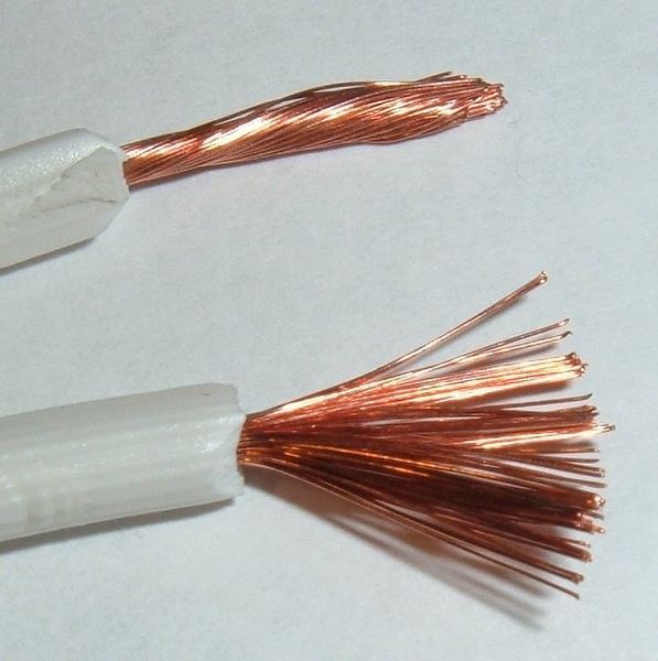
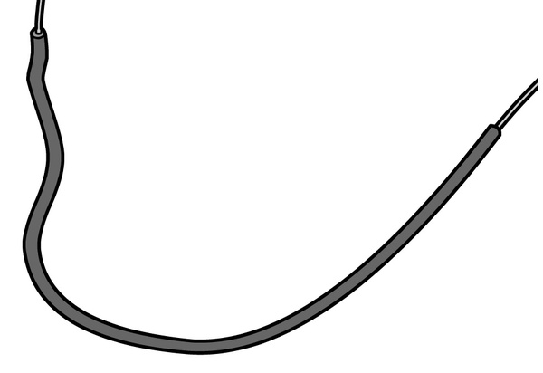
- Look carefully at the end of a piece of electric wire, or else look at the photo below.
- Examine the inside and outside of the wire.
QUESTIONS:
What are the two materials shown in this photo?
Inside: copper wire, Outside: coloured plastic material
Why does the wire have different materials on the inside and the outside? What are the functions of the inside and outside materials?
Inside: Copper wire is an electrical conducting material. It allows a path for an electric current in a circuit. Energy is transported in the copper wire from a battery to a device. Outside: Coloured plastic is an electrical insulating material. It prevents the transfer of energy to the environment. It is also there for safety purposes to prevent damage or shock if the electric current is large.
We have already discussed and constructed a switch, but a light switch in a house looks a bit different..
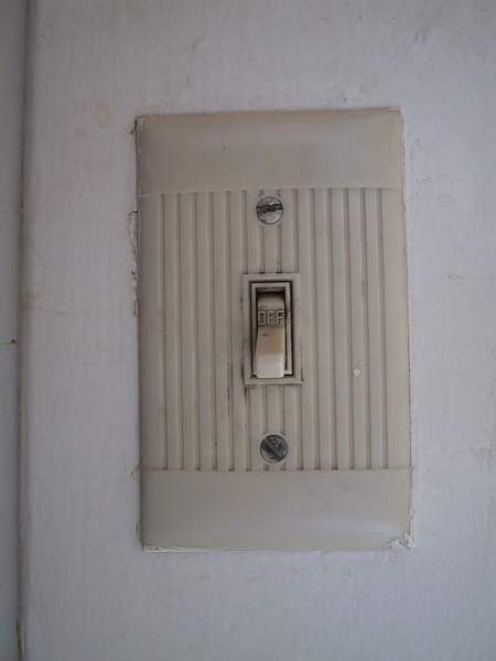
Describe in words how you think a light switch in your house works. Hint: look again how we made a switch with a paper clip.
When you flick the switch on, a connection is made (and the circuit is closed) meaning the light bulb will light up. When the switch is turned the other way (off), then the connection will be broken and the circuit will not transfer energy, meaning the light bulb will not light up.
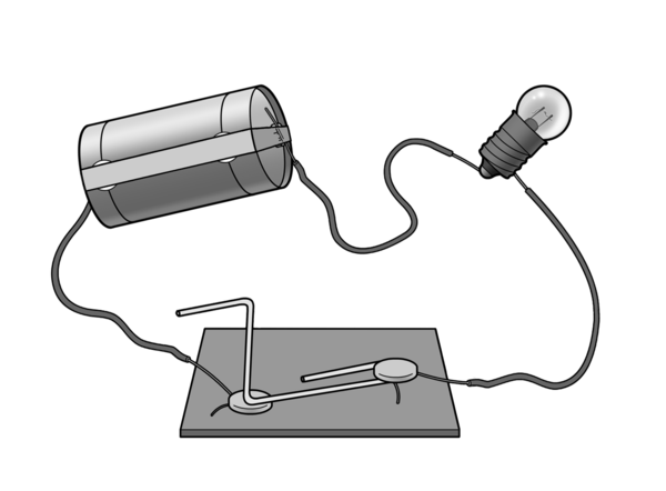
Circuit diagrams
If we want to keep a record of how we constructed a specific electric circuit, we can take a photo of it. If we do not have a camera, we can remember the circuit by drawing a sketch.
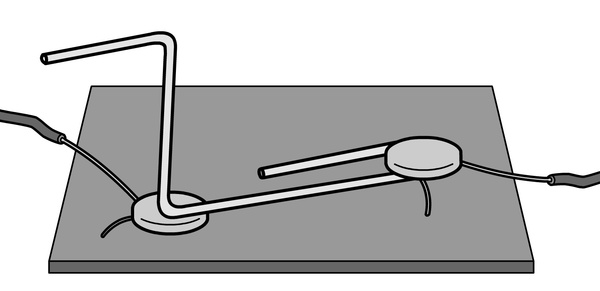
Look at the sketch below which Farrah drew of the circuit that you made in the activity with the paperclip switch.


That's right Jojo. It takes time to draw a sketch like this one that Farrah drew. It will even take longer if we add more components to a circuit. We could have more than one bulb like in the case of all the lights in your home. There could be also more than one switch. Each light in your home has its own switch.
And as Jojo pointed out, all of us do not draw equally well! To save time and to avoid bad sketches, scientists came up with a way of representing the components of a circuit with special symbols. These symbols are used all over the world. It helps scientists, engineers and technicians to draw or record circuits more quickly. It also helps everybody to understand the circuit in the same way.
The table shows the sketch Farrah drew and the symbol for each of the components of our circuit.
|
Component |
Sketch |
Symbol |
|
Battery |
 |
 |
|
Bulb |
 |
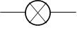 |
|
Electrical wire |
 |
_____ |
|
Switch |
 |
Open switch, circuit open:  Closed switch, circuit closed:  |
REMEMBER: a battery is made up of chemical cells. Sometimes people refer to batteries as cells, but in this book we will mostly use the term battery or batteries.

When we put these symbols together to represent an electric circuit, we call it a circuit diagram.
Draw a circuit diagram of the sketch above. Use the symbols in the table in place of sketching the components.
Compare your diagram with the one below. You might have drawn a diagram like the one below.
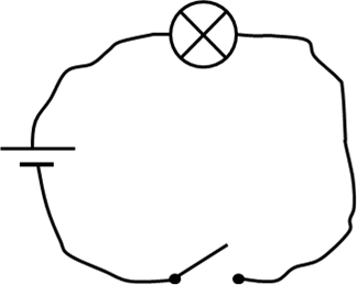
Take note that for electric circuit diagrams we represent the wires with straight lines.
This is a simple and quick way to represent an electric circuit and it should be clear to everyone that this circuit has a battery, a bulb and a switch, all connected with electric wires. Although we draw the wires as straight lines in a circuit diagram, remember that in real life, the wires are not straight. Just think of the electric wires that are attached to the appliances in your home, like to a kettle, a lamp, a vacuum cleaner or a computer.
Swap the components
Teacher note: In step 4 of the Learning Cycle, the teacher provides opportunities for learners to extend their understanding by providing new and/or related experiences for them to apply what they have learnt.
MATERIALS:
- circuit components (battery, wire, bulb, switch)
INSTRUCTIONS:
- Think again about our electric circuit and the diagram above. We have the battery on the left, the bulb at the top and the switch at the bottom.
- Assume we swap the bulb with the battery. The bulb is now on the left and the battery at the top.
-
First of all, draw the circuit diagram for such a setup.
-
Predict what will happen if you close the switch.
The bulb will light up with the same brightness as before.
-
Set up the circuit like this with the components you used before. Put the switch on and check if your prediction was correct. What do you conclude? Does it matter where in the circuit we position the components?
The sequence of the components in a simple circuit like the one used here is not important. The electric current will be the same in either case, since we did not change the battery (same power supply) or the bulb (same resistance).
Let's now practise drawing circuit diagrams.
Drawing circuit diagrams
INSTRUCTIONS
For each of the following, draw a circuit diagram in the space using all the components that are listed.
-
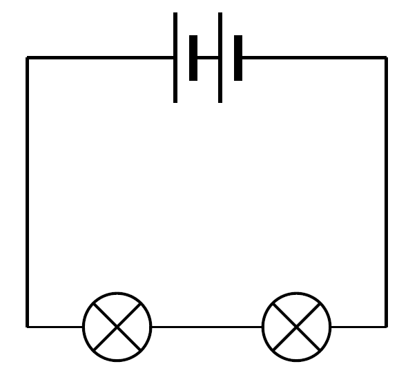
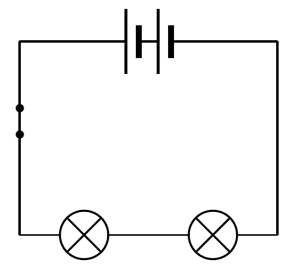
A circuit with 1 cell and 2 bulbs
-
A circuit with 2 cells and 2 bulbs
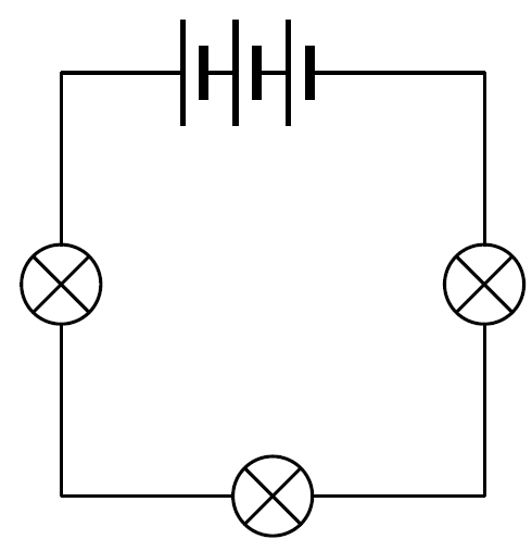
-
A circuit with 3 cells and 3 bulbs
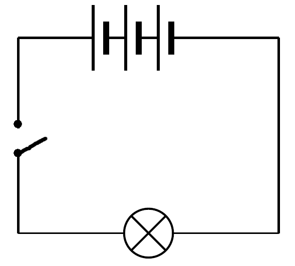
-
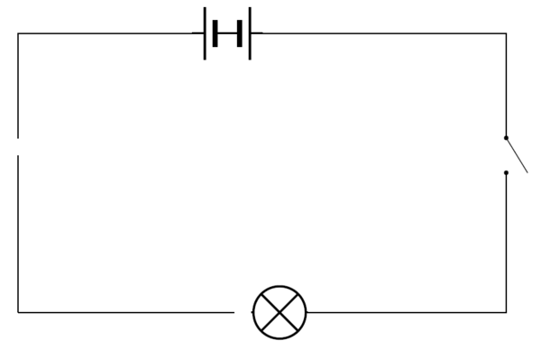
A circuit with 3 cells, a bulb and an open switch
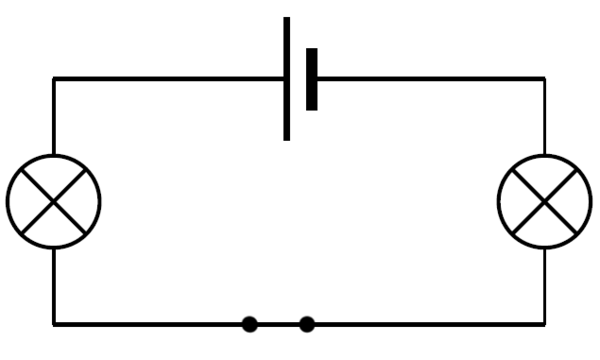
-
A circuit with 1 cell, 2 bulbs and a closed switch (the switch must be in between the bulbs)
More than one possible circuit can be drawn here. The given ones follow certain entrenched conventions. There is no reason why circuit 4 for example can't have alternating batteries and bulbs. The learners can even be asked to construct this circuit and observe if there is any noticeable difference in how the light bulbs behave. If they behave as before there is no real difference between the two circuits even though the connections are different.
1:
2:
3:
4:
5:
- An electric circuit is a system for transferring energy.
- A circuit is a complete and unbroken pathway for electricity.
- A simple circuit is made up of different components (a source of energy, conductors and a device).
- A circuit can have a switch to turn it on or off.
- Electric circuits can be drawn as circuit diagrams using symbols.
In step 5 of the Learning Cycle, the teacher assesses the learners' understanding.
Explain in your own words what an electric circuit is.
An electric circuit is a system for transferring electrical energy. It is a complete, unbroken path for electricity.
- What is the function of each electrical component in the table below?
|
Component |
Function |
|
Electric wire |
|
|
Battery |
|
|
Switch |
|
|
Bulb |
- In which of the following electric circuits will the bulb glow? Write yes or no next to each diagram. Write down a reason for your answer below the circuit.
|
Yes or no: |
Yes or no: |
 |
 |
|
Reason: |
Reason: |
|
Yes or no: |
Yes or no: |
 |
 |
|
Reason: |
Reason: |
- Draw a circuit diagram of the circuit shown below.
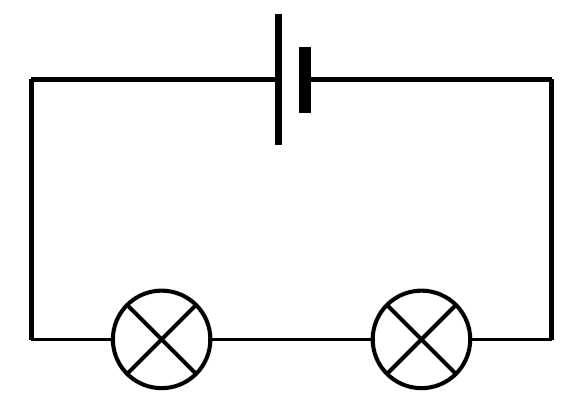
- Look at the following circuit diagram. Write down all the components represented in this circuit. Include the number of each component as well.
Two cells, two bulbs, a switch and 4 connecting electric wires.
-
The circuit diagram in question 5 represents a real circuit. In the real circuit, are the bulbs lit up? Why do you say so?
Yes, they are as the switch is closed.
Symbolic representation is new to learners at this level. Make it explicit that when we say `in the above circuit' we really mean 'in the actual circuit that this is a diagram of'.
- Look at the following circuit diagram. The bulb does not light up for four reasons. Draw a circle around the parts of the circuit that prevent the bulb from lighting up. Give a reason why the bulb doesn't light up in each case.
Batteries: one battery `pushes' current one way, the other the other way, so no current
Switch: open so current can't pass through it.
Light bulb: only one terminal connected to circuit, so no current can pass through it
Gap in circuit: no current can pass through it.
-
The circuit diagram in Question 7 represents a real circuit. Use the space below to draw what the real circuit might look like, if all the problems with the circuit were sorted out.

Ihope you enjoyed drawing circuit diagrams too!
Let's find out more about electrical components.